How-To install FC RX-7 front aluminum control arms.
Lets start with why:
This swap has the benefit of shaving 4lbs of weight per side off of the car in comparison to the weight of the JPM chromoloy MX-3 length control arms, which are supposed to be lighter than a stock MX-3 control arm. At this point IDK how much a standard BG arm weighs.
Potential problems:
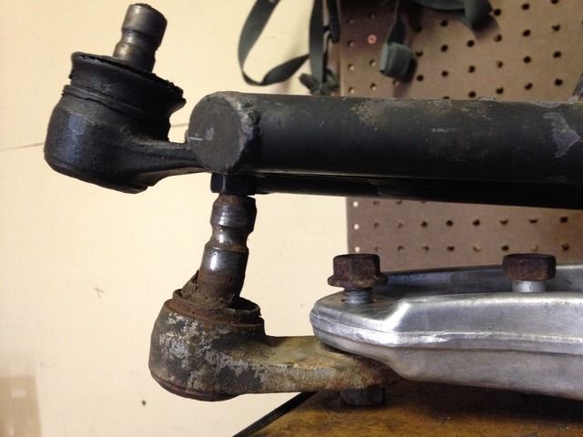
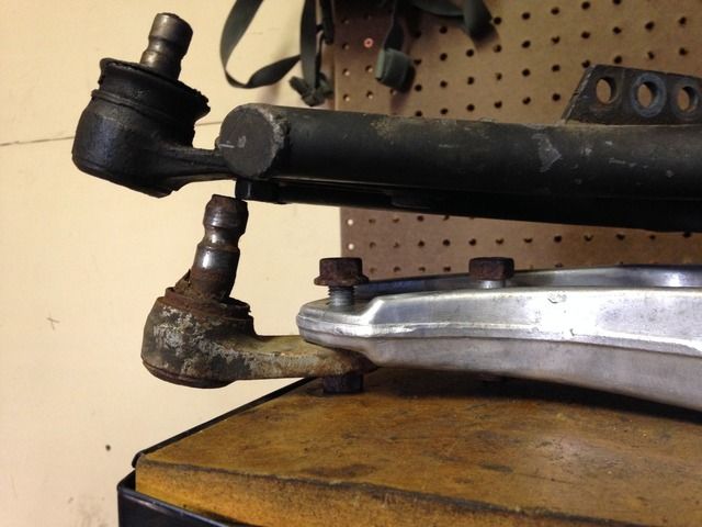
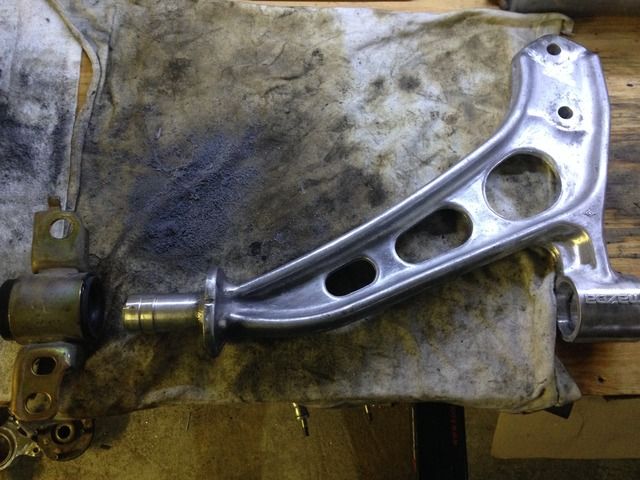
1: At this point the only potential problem is that this arm is a few inches shorter than the JPM arm I had on hand. With the arms sitting on top of each other and ball joints attached its about 1"-1 1/4" difference. Remove the additional 15mm/.6" that a MX-3 arm adds and it ends up being about 1/2" to 3/4" shorter.
2: The FC RX-7 ball joint must be used or some extended ball joints may be used to make the arms the same length. They can be found by looking for anyplace that sells FC drift parts.
3: A swaybar mount solution has to be fabricated. The FC normally has the sway bar mounted to a tab that bolts on with the ball joint but this would likely cause interference with the FWD axle since it would sit right under it. One solution is to run an endlink mounted to the strut tube like is used on the BJ protege. This has the advantage of increasing your sway bar rate since it changes the ratio. K-sport owners can just buy the sway bar mounts that thread onto the coilover bodies.
So with those things out of the way, this is obviously not a mod for everyone to attempt.
Cost: This kind of depends on the tools you have and how much of the work you do yourself and how good of a deal you find on the used control arms. If you do all the work your self and get a good deal on the control arms you should be able to do this for $100 or less with the price of the ES bushings.
Parts needed:
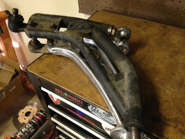
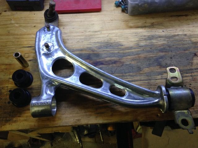
1: FC RX-7 control arms with bolt-on ball joints.
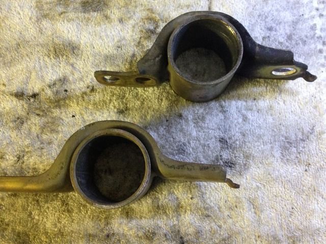
2: Control arm rear bushing shells from an MX3 that are 46mm ID. I got mine from a 92 MX-3.
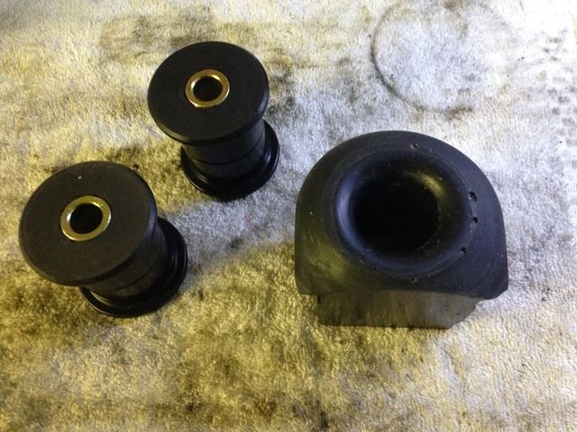
3: Energy suspension FC RX-7 control arm bushings
Tools:
1: Corded/cordless drill
2: Carbide burr bits and wire wheels
3: Hand tools to remove old control arms
4: Utility knife that uses replaceable razor blades.
5: 2" hole saw and 1 5/16" hole saw
6: shop press
Optional: drill press, lathe, air saw or mini sawzall
Step 1: Prep the arms
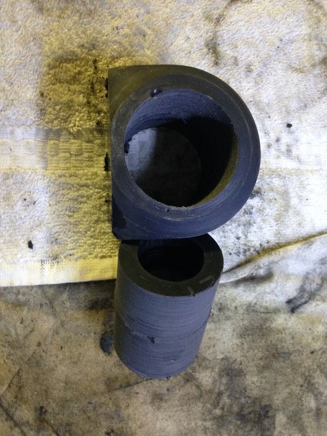
Start by pressing the bushings out of the control arms. The large rear bushing will have to be split since it has a metal sleeve inside. Clean them all up with your wire wheel after you finish. You will also need to trim some of the arm off near the rear bushing but I will cover that later.
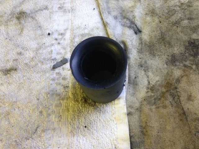
Step 2: Press the bushings out of the MX3 rear bushing shells. There will likely be a a metal sleeve that does not want to come out. You will need to split the metal sleeve to remove it.
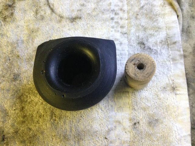
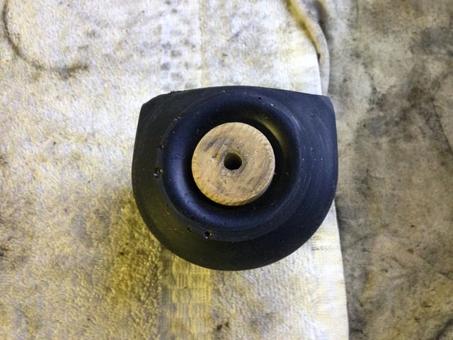
Step 3: You will need to take the 1 5"16 hole saw and drill out a couple of wood cores to insert into the large rear ES bushing. These cores will be used to guide the larger 2" hole saw as it cuts your new bushing out of the original. You can do this carefully with a corded/cordless drill or a better option would be to use a drill press if you have one
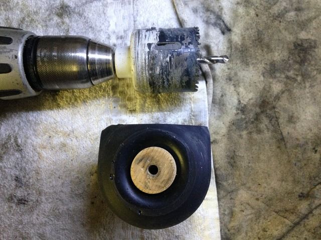
Step 4: Secure the bushing into a vise using the OEM bushing bracket if your arms came with them, but if not you can secure the bushing in the vise only snug enough to hold it but not distort it in any way. Start by drilling slowly in to the bushing avoiding excess speed or pressure to avoid melting the urethane. Once you start getting a little ways in the hole saw will get harder to turn and it will begin putting pressure on the bushing and trying to twist it. Just shoot some kind of WD-40 or equivalent into the drilling hole and it will reduce the friction. Once the saw reaches about half way, flip the bushing around and start drilling from the other side and make sure its straight otherwise the bushing wont be right. Once the bushing is drilled out it may not be 100% perfect but thats ok because its slightly oversized and will have to be trimmed down to 46mm OD to fit the MX3 shell.
Step 5: Now that you have finished the rear bushing its time to work on the front bushing. This time the bushing is designed as 2 pieces with a metal sleeve in the center. You will need to trim approx 2-3mm off one of the bushings or 1-1.5mm off each bushing. You will need to cut the metal sleeve down so that it is 57.3mm long.
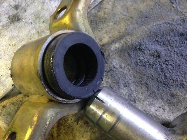
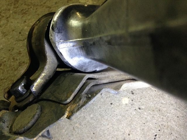
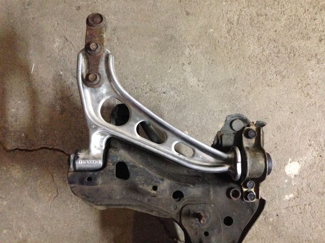
Step 6: Fit your bushings onto the control arm and test fit the arm onto the car subframe and trim if necessary. At this point you will notice part of the control arm will hit the subframe and not allow the rear bushing to bolt down. You will need to trim about 2-4mm off of the flange near the rear bushing over an area of about 90 degrees or more to allow the arm to move freely without hitting and allowing the bushing to bolt down completely.

Lets start with why:
This swap has the benefit of shaving 4lbs of weight per side off of the car in comparison to the weight of the JPM chromoloy MX-3 length control arms, which are supposed to be lighter than a stock MX-3 control arm. At this point IDK how much a standard BG arm weighs.
Potential problems:
1: At this point the only potential problem is that this arm is a few inches shorter than the JPM arm I had on hand. With the arms sitting on top of each other and ball joints attached its about 1"-1 1/4" difference. Remove the additional 15mm/.6" that a MX-3 arm adds and it ends up being about 1/2" to 3/4" shorter.
2: The FC RX-7 ball joint must be used or some extended ball joints may be used to make the arms the same length. They can be found by looking for anyplace that sells FC drift parts.
3: A swaybar mount solution has to be fabricated. The FC normally has the sway bar mounted to a tab that bolts on with the ball joint but this would likely cause interference with the FWD axle since it would sit right under it. One solution is to run an endlink mounted to the strut tube like is used on the BJ protege. This has the advantage of increasing your sway bar rate since it changes the ratio. K-sport owners can just buy the sway bar mounts that thread onto the coilover bodies.
So with those things out of the way, this is obviously not a mod for everyone to attempt.
Cost: This kind of depends on the tools you have and how much of the work you do yourself and how good of a deal you find on the used control arms. If you do all the work your self and get a good deal on the control arms you should be able to do this for $100 or less with the price of the ES bushings.
Parts needed:
1: FC RX-7 control arms with bolt-on ball joints.
2: Control arm rear bushing shells from an MX3 that are 46mm ID. I got mine from a 92 MX-3.
3: Energy suspension FC RX-7 control arm bushings
Tools:
1: Corded/cordless drill
2: Carbide burr bits and wire wheels
3: Hand tools to remove old control arms
4: Utility knife that uses replaceable razor blades.
5: 2" hole saw and 1 5/16" hole saw
6: shop press
Optional: drill press, lathe, air saw or mini sawzall
Step 1: Prep the arms
Start by pressing the bushings out of the control arms. The large rear bushing will have to be split since it has a metal sleeve inside. Clean them all up with your wire wheel after you finish. You will also need to trim some of the arm off near the rear bushing but I will cover that later.
Step 2: Press the bushings out of the MX3 rear bushing shells. There will likely be a a metal sleeve that does not want to come out. You will need to split the metal sleeve to remove it.
Step 3: You will need to take the 1 5"16 hole saw and drill out a couple of wood cores to insert into the large rear ES bushing. These cores will be used to guide the larger 2" hole saw as it cuts your new bushing out of the original. You can do this carefully with a corded/cordless drill or a better option would be to use a drill press if you have one
Step 4: Secure the bushing into a vise using the OEM bushing bracket if your arms came with them, but if not you can secure the bushing in the vise only snug enough to hold it but not distort it in any way. Start by drilling slowly in to the bushing avoiding excess speed or pressure to avoid melting the urethane. Once you start getting a little ways in the hole saw will get harder to turn and it will begin putting pressure on the bushing and trying to twist it. Just shoot some kind of WD-40 or equivalent into the drilling hole and it will reduce the friction. Once the saw reaches about half way, flip the bushing around and start drilling from the other side and make sure its straight otherwise the bushing wont be right. Once the bushing is drilled out it may not be 100% perfect but thats ok because its slightly oversized and will have to be trimmed down to 46mm OD to fit the MX3 shell.
Step 5: Now that you have finished the rear bushing its time to work on the front bushing. This time the bushing is designed as 2 pieces with a metal sleeve in the center. You will need to trim approx 2-3mm off one of the bushings or 1-1.5mm off each bushing. You will need to cut the metal sleeve down so that it is 57.3mm long.
Step 6: Fit your bushings onto the control arm and test fit the arm onto the car subframe and trim if necessary. At this point you will notice part of the control arm will hit the subframe and not allow the rear bushing to bolt down. You will need to trim about 2-4mm off of the flange near the rear bushing over an area of about 90 degrees or more to allow the arm to move freely without hitting and allowing the bushing to bolt down completely.


Comment