Announcement

Collapse
No announcement yet.

GI: YCW Reference Series Coilovers

Collapse
X
 
  • Filter
  • Time
  • Show
Clear All
new posts

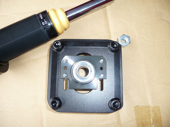
    Let's try this again. This is the mount . You telling me it's not offset. U can clearly see the bigger gap at the bottome than top and u telling me that's because of caster adjustment bracket.... oh wait left to right is different widths as well. But yet it's not offset but because of adjustment plate ?

    [/QUOTE]

    Comment


      Yes, it is offset in the image (I have said that, twice)

      Top/Bottom is camber
      Left/Right is caster

      If you want the ball-joint centred, then you can adjust it in all 4 directions till you get it to sit how you require.

      "Centred" is in relation to the 4 studs, not the shape/gap on the top mount
      Last edited by MFactory; 09-03-2017, 02:51 PM.
      MFactory / YCW Engineering (LSD's, Gears, Flywheels, Clutches, Driveshafts, Axles) - www.teammfactory.com
      YCW Suspension (Mid-Range Coilovers) - www.ycwsuspension.com
      SWIFT Springs Europe (Exclusive Distributor) - www.swiftspringseurope.com
      SWIFT Springs Asia (Exclusive Distributor) - www.swiftspringsasia.com

      Comment


        Proper centered camber plate see how it's equally distant
        Click image for larger version

Name:	Screenshot_20170903-160856.jpg
Views:	1
Size:	80.9 KB
ID:	1245094

        Ycw Off Center plate that are not equally distant
        Click image for larger version

Name:	p1070649.jpg
Views:	1
Size:	44.9 KB
ID:	1245095

        All other coilovers / camber mounts are centered like the blue one pictured. And my understanding was that the final product was supposed to be corrected and centered as above picture after a conversation with the engineer that i bet never happend. The design is wrong and were told to correct several times.

        Comment


          Look at the image you posted of the blue top mount. Look at the ball joint and how it is "centred" within the 4 studs. DISREGARD the blue portion of the top mount. Just look at the ball joint and the 4 studs. Now, what happens if you move the ball joint? Yup, you guessed it, it is now "offset".

          Now, look at the image of our top mount. What happens if you move the ball joint and/or the caster bracket so that the ball joint is "centred" within the 4 studs (again, DISREGARD the black portion of the top mount)? Yup, you guessed it, it is now "centred".

          The Blue or Black portion of the top mount could be shaped like Mickey Mouse, but that doesn't change how the ball joint is positioned relevant to the 4 studs. THAT is what matters, and is how camber/caster is adjusted

          I'm sorry if you don't understand anything that I said in my replies to you explaining how to "centre" the ball joint, but I honestly don't know how else to explain it to you.

          And I'm sorry that you think that I'm constantly lying to you, and that I don't talk to the engineer with regards to changes, or I'm deliberately delaying shipments/production so that I can add other orders on etc etc

          Seriously, enough, please...
          Last edited by MFactory; 09-03-2017, 04:04 PM.
          MFactory / YCW Engineering (LSD's, Gears, Flywheels, Clutches, Driveshafts, Axles) - www.teammfactory.com
          YCW Suspension (Mid-Range Coilovers) - www.ycwsuspension.com
          SWIFT Springs Europe (Exclusive Distributor) - www.swiftspringseurope.com
          SWIFT Springs Asia (Exclusive Distributor) - www.swiftspringsasia.com

          Comment


            Originally posted by MFactory View Post
            I never said anything about camera angle. I said "It just looks off-centre in the image because of how the studs/caster is positioned"

            The holes on the top mount are elongated, so depending on where the studs/caster bracket is positioned in relation to the top mount, the ball joint "may" or "may not" be off-centre

            If you do not set it to positive caster, then the ball-joint will be centred in relation to the studs, otherwise, it will be off-centre (like in the image)
            Correct.

            The top mount as pictured is "upside down" in the context of it how it would appear in top view when mounted in position on the car. The top mount would also be flipped so that the slots run top to bottom (in the context of the picture) not side to side as shown.

            The top mount when placed in position and bolted in place is "pinched" in place or sandwiched between the U shaped bracket with the mounting studs and the underside of the strut mounting position.

            The top mount must obviously be orientated correctly (when mounted up to the car) so that it can be adjusted along the slots to dial in the positive/neutral/negative caster setting required for the set up.

            Sorry MFactory; I should have posted this picture up in the first place.


            Last edited by projectb10; 09-03-2017, 05:35 PM.

            Comment


              Originally posted by projectb10 View Post
              Correct.

              The top mount as pictured is "upside down" in the context of it how it would appear in top view when mounted in position on the car. The top mount would also be flipped so that the slots run top to bottom (in the context of the picture) not side to side as shown.

              The top mount when placed in position and bolted in place is "pinched" in place or sandwiched between the U shaped bracket with the mounting studs and the underside of the strut mounting position.

              The top mount must obviously be orientated correctly (when mounted up to the car) so that it can be adjusted along the slots to dial in the positive/neutral/negative caster setting required for the set up.

              Sorry MFactory; I should have posted this picture up in the first place.

              Thanks for helping to clarify
              MFactory / YCW Engineering (LSD's, Gears, Flywheels, Clutches, Driveshafts, Axles) - www.teammfactory.com
              YCW Suspension (Mid-Range Coilovers) - www.ycwsuspension.com
              SWIFT Springs Europe (Exclusive Distributor) - www.swiftspringseurope.com
              SWIFT Springs Asia (Exclusive Distributor) - www.swiftspringsasia.com

              Comment


                Click image for larger version

Name:	IMG_3105.JPG
Views:	1
Size:	278.0 KB
ID:	1245096Click image for larger version

Name:	IMG_3106.JPG
Views:	1
Size:	253.0 KB
ID:	1245097

                We have a problem. See the attached images if they will work.

                Due to the changes in your production parts the spring that would work before is now too long. Since your lower perch is thicker and the upper perch is deeper, I can't achieve the same ride height before everything is touching and can't be adjusted any further.


                Sent from my iPhone using Tapatalk
                92 Mazda MX3 GS> For sale, $1750 OBO
                94 Escort wagon--BP swap coming, VF10 Turbo, COP, EVO ECU, 03 ZX2 front end conversion
                "Hold yourself accountable before you are held accountable"
                EV14 330cc@3Bar injector kits available.
                EV14 GT500 injector kits available for the BP. 610cc@3Bar.
                EV14 925cc@3Bar injector kits available
                BP Forged H beam rods available now
                KL Forged H beam rods available now
                K8/KF Forged H beam rods awaiting test fit
                FS Forged H beam rods
                awaiting test fit
                F2 Forged H beam rods awaiting test fit
                FE3 Forged H beam rods coming soon
                Mitsubishi 3.8 MIVEC rods coming soon
                Aluminum CAS/Distributor caps
                BP oil jet eliminators
                EV14 fuel rail spacers
                More stuff coming soon.......

                Comment


                  How far off your original ride height are you?
                  MFactory / YCW Engineering (LSD's, Gears, Flywheels, Clutches, Driveshafts, Axles) - www.teammfactory.com
                  YCW Suspension (Mid-Range Coilovers) - www.ycwsuspension.com
                  SWIFT Springs Europe (Exclusive Distributor) - www.swiftspringseurope.com
                  SWIFT Springs Asia (Exclusive Distributor) - www.swiftspringsasia.com

                  Comment


                    Hard to say without installing them, but in the picture I would still have go down more on the spring perch since at its current position I have to compress the spring to seat the top perch on the shaft, more then the standard "snug" pre-load


                    Sent from my iPhone using Tapatalk
                    92 Mazda MX3 GS> For sale, $1750 OBO
                    94 Escort wagon--BP swap coming, VF10 Turbo, COP, EVO ECU, 03 ZX2 front end conversion
                    "Hold yourself accountable before you are held accountable"
                    EV14 330cc@3Bar injector kits available.
                    EV14 GT500 injector kits available for the BP. 610cc@3Bar.
                    EV14 925cc@3Bar injector kits available
                    BP Forged H beam rods available now
                    KL Forged H beam rods available now
                    K8/KF Forged H beam rods awaiting test fit
                    FS Forged H beam rods
                    awaiting test fit
                    F2 Forged H beam rods awaiting test fit
                    FE3 Forged H beam rods coming soon
                    Mitsubishi 3.8 MIVEC rods coming soon
                    Aluminum CAS/Distributor caps
                    BP oil jet eliminators
                    EV14 fuel rail spacers
                    More stuff coming soon.......

                    Comment


                      The reason for the longer springs was to try to keep any coil-bind at a minimum over bumps. If you go for a shorter spring, you "may" also need to go up a spring rate to compensate.

                      What we might need to do is forego the 1pc lower spring perch in favour of the regular 2pc lower spring perch for those who may have the same lowering height issue.

                      Could you give it a try, and maybe post up a few images of the car sitting at the lowest height setting? If you could also try to snap an image of the spring as well (under load) so I can see how much spring travel there is left. If this is sufficient, you may not need to go up a spring rate with a shorter spring.
                      MFactory / YCW Engineering (LSD's, Gears, Flywheels, Clutches, Driveshafts, Axles) - www.teammfactory.com
                      YCW Suspension (Mid-Range Coilovers) - www.ycwsuspension.com
                      SWIFT Springs Europe (Exclusive Distributor) - www.swiftspringseurope.com
                      SWIFT Springs Asia (Exclusive Distributor) - www.swiftspringsasia.com

                      Comment


                        Click image for larger version

Name:	IMG_3064.JPG
Views:	1
Size:	339.5 KB
ID:	1245098Click image for larger version

Name:	IMG_2495.JPG
Views:	1
Size:	251.5 KB
ID:	1245099

                        That's how it sat before I pulled them. I am not super low as I can still get 1 finger between the fender and tire.

                        As for a compressed shot I will try to get one tonight.


                        Sent from my iPhone using Tapatalk
                        92 Mazda MX3 GS> For sale, $1750 OBO
                        94 Escort wagon--BP swap coming, VF10 Turbo, COP, EVO ECU, 03 ZX2 front end conversion
                        "Hold yourself accountable before you are held accountable"
                        EV14 330cc@3Bar injector kits available.
                        EV14 GT500 injector kits available for the BP. 610cc@3Bar.
                        EV14 925cc@3Bar injector kits available
                        BP Forged H beam rods available now
                        KL Forged H beam rods available now
                        K8/KF Forged H beam rods awaiting test fit
                        FS Forged H beam rods
                        awaiting test fit
                        F2 Forged H beam rods awaiting test fit
                        FE3 Forged H beam rods coming soon
                        Mitsubishi 3.8 MIVEC rods coming soon
                        Aluminum CAS/Distributor caps
                        BP oil jet eliminators
                        EV14 fuel rail spacers
                        More stuff coming soon.......

                        Comment


                          Ok instead of going through installing these and trying to guess at compression and how much is usable from a picture, lets just measure and use specs.

                          You have about 5" of stroke on your dampers and then if you factor in the bump stop we can say 4"...

                          With that in mind this is the front spring we are using in RED, or if its not give me the part number as I cant find the box they came in:
                          Part # Spring Rate Usable Stroke Max Stroke Max. Load
                          kgf/mm lbs/inch mm inch mm inch kgf lbs
                          Z65-203-040 4.0 224 132 5.2 139 5.5 557 1,228
                          Z65-203-050 5.0 280 126 5.0 133 5.2 666 1,468

                          Based off this we will hit the bump stop before we bottom this spring out.

                          On the other hand if we go to a 7" spring instead of the current 8" in the same 5K rate: We are still going to be hitting the bump stop before we use up the usable stroke.
                          Part # Spring Rate Usable Stroke Max Stroke Max. Load
                          kgf/mm lbs/inch mm inch mm inch kgf lbs
                          Z65-178-040 4.0 224 120 4.7 122 4.8 487 1,074
                          Z65-178-050 5.0 280 110 4.3 121 4.7 603 1,329

                          I can assure you that even fully loaded and hitting a few hard bumps that I wasnt close to hitting the bump stops or using up the travel and from the marks on the spring it only bound the very bottom coil.

                          If you insist on using a 5K spring then you will be fine with using a 1" shorter spring although I still personally feel that you should be at least using a 6K spring in front.

                          Also BTW, this Castor adjustment plate you guys have is very annoying. Trying to hold it in place while putting the nuts on the top mount is cumbersome or if somebody wants to install a strut tower bar later on and you take the nuts off it will fall off. A traditional Camber/Castor plate would have been a far better choice.
                          92 Mazda MX3 GS> For sale, $1750 OBO
                          94 Escort wagon--BP swap coming, VF10 Turbo, COP, EVO ECU, 03 ZX2 front end conversion
                          "Hold yourself accountable before you are held accountable"
                          EV14 330cc@3Bar injector kits available.
                          EV14 GT500 injector kits available for the BP. 610cc@3Bar.
                          EV14 925cc@3Bar injector kits available
                          BP Forged H beam rods available now
                          KL Forged H beam rods available now
                          K8/KF Forged H beam rods awaiting test fit
                          FS Forged H beam rods
                          awaiting test fit
                          F2 Forged H beam rods awaiting test fit
                          FE3 Forged H beam rods coming soon
                          Mitsubishi 3.8 MIVEC rods coming soon
                          Aluminum CAS/Distributor caps
                          BP oil jet eliminators
                          EV14 fuel rail spacers
                          More stuff coming soon.......

                          Comment


                            Originally posted by KAinjection View Post
                            ......With that in mind this is the front spring we are using in RED, or if its not give me the part number as I cant find the box they came in:.........

                            Part Number: Z65-203-050
                            Spring Rate: 5 kgf/mm 279.9842 lbs/inch
                            Usable Stroke: 126m / 4.96062992125984 inch
                            Max Stroke: 133.2mm / 5.24409448818898 inch
                            Max Load: 666 kgf / 1468.2636 lbs

                            Part Number: Z65-228-040
                            Spring Rate: 4kgf/mm 223.98736lbs/inch
                            Usable Stroke: 98m / 4 inch
                            Max Stroke: 158.7mm / 6.24803149606299inch
                            Max Load: 634.8 kgf / 1399.48008lbs

                            Comment


                              A couple simple ideas that would solve the castor adjuster-falling-apart problem... might work well on future batches of these and maybe your other platforms too if they are designed the same way:
                              • Use pressed-in studs instead of socket head cap screws.
                              • Put a couple small (like, 5mm wide) slots in the center section of the U shaped piece. Slot should be the same length as the slotted holes in the main strut mount.
                              • Use corresponding short M5 button-head screws & washers to lock the U-shaped piece to tapped holes in the camber plate.
                              • If you set this up with the base of the U facing outboard, you could easily access these small screws to loosen them when you want to adjust caster.
                              • Otherwise, they stay tight and your caster setting won’t change/things won’t fall apart when you remove your strut tower bar.


                              To prevent the falling apart problem on existing units, pushing a couple of these onto the top side between the body and your STB. would at least prevent parts from falling, although removing your strut tower bar could still result in an alignment change. https://www.fastenal.com/products/details/11264795 (not 100% sure this is the right size). Personally i'm just going to use two nuts (as i've always done anyway), one to secure the suspension to the car and a second set to secure the strut tower bar.

                              I think it makes complete sense that the center of the plate is offset. There is no reason why anyone would ever want less caster than the BG comes with stock (and if they do for some crazy reason, swap sides!). So, maxed out in one direction = centered = stock caster. All of your adjustability is in the other direction, yielding more adjustability than would otherwise be possible.

                              Back to the spring discussion
                              Escort GTR -- 11.87 @ 117.6 mph -- 320 HP / 325 Ft. Lbs. @ 23 PSI
                              ... The first FWD BG with a Toyota E153 transmission conversion in the USA!
                              Looking for BP x Toyota E153 adapter plates? PM me or contact me on Facebook: Riel Performance Parts

                              Comment


                                Originally posted by therieldeal View Post
                                A couple simple ideas that would solve the castor adjuster-falling-apart problem... might work well on future batches of these and maybe your other platforms too if they are designed the same way:
                                • Use pressed-in studs instead of socket head cap screws.
                                • Put a couple small (like, 5mm wide) slots in the center section of the U shaped piece. Slot should be the same length as the slotted holes in the main strut mount.
                                • Use corresponding short M5 button-head screws & washers to lock the U-shaped piece to tapped holes in the camber plate.
                                • If you set this up with the base of the U facing outboard, you could easily access these small screws to loosen them when you want to adjust caster.
                                • Otherwise, they stay tight and your caster setting won’t change/things won’t fall apart when you remove your strut tower bar.


                                To prevent the falling apart problem on existing units, pushing a couple of these onto the top side between the body and your STB. would at least prevent parts from falling, although removing your strut tower bar could still result in an alignment change. https://www.fastenal.com/products/details/11264795 (not 100% sure this is the right size). Personally i'm just going to use two nuts (as i've always done anyway), one to secure the suspension to the car and a second set to secure the strut tower bar.

                                I think it makes complete sense that the center of the plate is offset. There is no reason why anyone would ever want less caster than the BG comes with stock (and if they do for some crazy reason, swap sides!). So, maxed out in one direction = centered = stock caster. All of your adjustability is in the other direction, yielding more adjustability than would otherwise be possible.

                                Back to the spring discussion
                                Logical thinking. Thank you.

                                Sent from my SM-G955U using Tapatalk
                                My car is a Vazondissan. Part Nissan. Part Mazda. Part Ford. Part VW. Part Honda.

                                1993 Protege - DX with LX upgrades. Still rockin' the SOHC. Custom HID headlight Retrofit.

                                2009 Mazda 3 - Finacee Car. No power nothing. About to trade in for a 2014 Mazda 6 Sport.

                                Install Shifter Bushings: http://www.wihandyman.com/forum/show...491#post646491

                                Custom HID's: http://www.wihandyman.com/forum/show...&highlight=hid

                                Comment

                                Working...
                                X